How to Test Capacitors Without an ESR Meter (Bulging, Leakage, and Value)
Picture a PC power supply that runs for twenty minutes, reboots at random, and refuses to start again until it has cooled down. Someone checks the five output capacitors with a handheld capacitance meter and every one reads within 5% of its 2,200 µF label, so the capacitors get cleared and the hunt moves on to the controller chip. That is a very common way to lose an afternoon.
The catch is that capacitance is only half the story. A capacitor that has been baked by a nearby heatsink can still read the right number of microfarads while its internal resistance (ESR) has climbed to 15 Ω or more. At switching frequencies that resistance causes heavy ripple, the supply rail sags, and the protection circuit shuts everything down as soon as the unit warms up.
This guide shows how to find failing capacitors with an ordinary multimeter, your eyes and a few basic bench tools: what a bad one looks like, how to discharge one safely, what the capacitance and ohmmeter tests can and cannot tell you, and what to do when you do not own an ESR meter.
Contents in this Guide
- Why Capacitors Fail (and Which Ones Fail First)
- Safety and Discharge First
- Visual Inspection (Free and Often Enough)
- Testing Capacitance with a Multimeter
- Testing for Shorts and Leakage with an Ohmmeter
- Testing ESR Without an ESR Meter
- Reading a Capacitor's Reactance and Time Constant (Quick Math)
- Motor Start/Run, Film, and Special Capacitors
- A Repeatable Bench Workflow
- Choosing a Replacement
- Common Mistakes That Ruin Your Diagnosis
- Interactive Tools & Bench Quiz
- Related ElectroLab Calculators & Guides
- Frequently Asked Questions
Why Capacitors Fail (and Which Ones Fail First)
Aluminum electrolytic capacitors are the one common passive part on a circuit board that contains a liquid, and that liquid slowly dries out. Inside an aluminum electrolytic capacitor, two thin strips of etched aluminum foil are separated by porous paper soaked in a conductive liquid electrolyte.
Over years of operation, five environmental stresses degrade this chemical balance:
- Thermal Baking: Heat is the biggest killer. The Arrhenius rule of chemical reaction rates dictates that for every 10°C rise in operating temperature, a capacitor's lifespan is cut in half. A capacitor rated for 2,000 hours at 105°C will last over 30,000 hours at 65°C, but cooking next to an unventilated 90°C heatsink kills it in months.
- Ripple Current Stress: Switch-mode power supplies charge and discharge their output capacitors tens of thousands of times per second. That ripple current heats the capacitor through its own internal resistance (I²R).
- Electrolyte Desiccation: As heat rises, the liquid electrolyte slowly turns into vapor and escapes past the rubber sealing bung at the bottom of the can. As the electrolyte dries, internal conductivity plummets.
- Voltage Overstress: Transient voltage spikes punch microscopic pinholes through the thin aluminum oxide dielectric layer, causing internal micro-arcing and gas formation.
Capacitance vs ESR: Why Value Alone Is Not Enough
A standard digital multimeter measures capacitance by pumping a known DC current into the capacitor, timing how long the voltage takes to rise, and calculating C = (I × Δt) / ΔV.
The meter does this at DC or a very low frequency. But inside a switching power supply or audio amplifier, the capacitor must filter high-frequency AC ripple. Equivalent Series Resistance (ESR) represents the total internal ohmic resistance of the aluminum foil, lead wire tabs, and liquid electrolyte.
When an electrolytic capacitor begins to dry out, its ESR often climbs from a healthy 0.04 Ohms to 8.0 Ohms or 25.0 Ohms while the total plate surface area remains intact. Your multimeter will happily report that a 1,000 µF capacitor still measures 980 µF, yet on the circuit board, that 10 Ohm internal resistance blocks ripple current, boils the remaining electrolyte, and leaves the power rail noisy and unstable.
Where Failures Hide on the Board
On failed boards, bad capacitors tend to cluster in three places:
- Immediately Adjacent to Heatsinks: Designers often squeeze secondary filter capacitors right up against the aluminum heatsinks of Schottky diodes and MOSFETs. The radiated heat cooks the rubber bung.
- SMPS Startup Auxiliary Capacitors: In switch-mode power supplies, look for a tiny 10 µF to 47 µF electrolytic capacitor sitting right next to the PWM controller IC. When this small capacitor dries out, the supply gets stuck in a continuous clicking "hiccup mode" restart loop. (Review our SMPS Repair & Troubleshooting Guide for detailed startup circuit diagnostics).
- Induction Cooker Resonant Capacitors: Large polypropylene film capacitors subjected to continuous 25 kHz resonant pulses. If they lose value, the IGBT fails immediately. (See our Induction Cooker IGBT Repair Guide).
Safety and Discharge First
High-voltage bulk capacitors found in switch-mode power supplies, solar inverters, induction cooktops, and microwave ovens can store lethal electrical energy at 300V to 4,000V DC long after the mains cord is disconnected from the wall.
Never short high-voltage capacitor terminals with a bare screwdriver. The arc can throw molten metal, damage the terminals and the board, and may leave part of the charge behind. Use a dedicated power resistor with insulated clip leads, wait for the discharge, and confirm 0.0 V with a multimeter before touching any lead.
How much energy is stored, and how long does a safe discharge take?
Take a 400 V, 470 µF bulk capacitor from an offline power supply, discharged through a 10 kΩ, 5 W power resistor:
C = 470 µF = 0.00047 Farads
Stored Energy = 0.5 × 0.00047 × 400² = 0.5 × 0.00047 × 160,000 = 37.60 Joules
Initial Discharge Current = 400 V / 10,000 Ω = 0.040 Amps (40.0 mA)
Peak Resistor Power = 400² / 10,000 Ω = 160,000 / 10,000 = 16.0 Watts
Time Constant (τ) = 10,000 Ω × 0.00047 F = 4.70 Seconds
Safe 99.3% Discharge Time (5τ) = 5 × 4.70 s = 23.50 Seconds
Notice that the initial instantaneous power across the resistor is 16 Watts. The power falls off quickly as the voltage drops, and about 38 J in total is spread over several seconds, so a 5 to 10 W wirewound or ceramic power resistor copes with it. Check the resistor datasheet if you use a smaller part. After 24 seconds, the voltage drops to under 3 Volts, safe to handle. Always verify with your meter set to DC Volts before soldering. (For microwave oven capacitor discharge procedures at 2,000V+, refer to our Microwave Oven Repair Guide).
Visual Inspection (Free and Often Enough)
Before you desolder anything, look over the board under bright light, with a magnifier if you have one. Visible damage settles many cases within half a minute.
What You See: The Four Tell-Tale Visual Signs
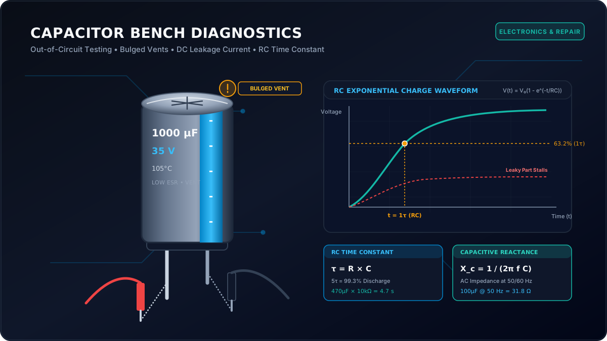
- Convex Domed or Bulged Tops: Manufacturers stamp criss-cross (X, K, or Y) score lines into the top aluminum disc. This is a deliberate safety pressure relief vent. If pressure builds up inside, the metal dome expands upward rather than blowing the can apart like a firecracker. If the top is even slightly domed rather than razor-flat, the capacitor is dead.
- Split Vents and Crusty Residue: If internal pressure exceeded the rupture point, the score lines split open, releasing dried brown, white, or crusty electrolyte across the aluminum top.
- Pushed-Out Bottom Rubber Bung: Sometimes the top vent does not rupture, but the rubber sealing bung at the bottom pushes outward, causing the capacitor to tilt crookedly on the circuit board.
- Corroded Component Leads and Dark PCB Stains: Leaked electrolyte is mildly acidic or alkaline. It eats through the protective green solder mask, turns copper traces dull black, and corrodes adjacent surface-mount resistor legs.
| What You See | What It Usually Means | Replace? | Bench Notes |
|---|---|---|---|
| Flat aluminum top, clean rubber bung | Normal physical condition | Maybe | Can still have high ESR or low capacitance; requires electrical testing |
| Slightly domed / convex top vent | Internal gas pressure from overheating or ripple | Yes, Immediately | Do not bother testing; electrolyte has degraded permanently |
| Ruptured score lines with brown crust | Catastrophic vent failure and electrolyte loss | Yes, Immediately | Clean acidic residue from PCB traces with isopropyl alcohol |
| Rubber bung pushed out; cap tilted | Bottom seal blown from internal pressure | Yes, Immediately | Often pulls solder pads or stresses PCB traces |
| Shrunk or blackened plastic vinyl sleeve | Severe sustained operating heat (> 110°C) | Yes, Immediately | The entire capacitor has been thermally baked dry |
| Yellow / white silicone glue around base | Factory anti-vibration staking adhesive | No | Common false alarm; factory glue is rubbery, while dried electrolyte is hard and crusty |
Reading the Markings on the Can
Every through-hole radial electrolytic capacitor carries four essential ratings printed on its vinyl sleeve:
- Capacitance Value: Stated in microfarads (e.g.,
1000 µF,470 µF,22 µF). - DC Working Voltage Rating: The maximum continuous voltage the capacitor can withstand (e.g.,
16V,25V,50V,400V). Operating above this voltage punches through the dielectric oxide. - Temperature Rating: Standard consumer parts are rated for
85°C. Professional and power supply parts are rated for105°Cor125°C. Always use 105°C rated replacements in power supplies. - Polarity Stripe: On aluminum electrolytic capacitors, a thick vertical white, silver, or gold stripe with minus signs (
-) runs down the side of the negative cathode lead.
Testing Capacitance with a Multimeter
If your digital multimeter features a dedicated capacitance mode (indicated by the capacitor schematic symbol -[(- or microfarad ranges), you can measure the actual stored charge capability directly.
Step-by-Step Out-of-Circuit Test
Never attempt to measure capacitance on a circuit board with both leads soldered in place. Follow this four-step bench procedure:
- Discharge completely: Confirm 0.0 V across the terminals with a DC voltmeter.
- Desolder at least one lead: Use a soldering iron and desoldering pump or wick to lift at least one terminal completely out of the circuit board. This isolates the capacitor from parallel components.
- Zero your multimeter: With your test leads open in the air, press the
REL(Relative) orZERObutton on your meter to cancel out the natural 10 pF to 40 pF stray capacitance of your probe wires. - Connect with correct polarity: Place the red probe on the positive lead and the black probe on the striped negative lead. Wait a few seconds for the meter to charge the component and stabilize its digital display.
| Meter Reading | What It Means | Verdict | Next Bench Step |
|---|---|---|---|
| Within ± 20% of marked value | Capacitance meets factory tolerance | Pass (Value only) | Perform resistance charge check; test for ESR if in a high-frequency supply |
| Low by more than 20% | Significant electrolyte loss or foil erosion | Fail | Replace part immediately |
| Reads zero, < 1 pF, or Open Loop (OL) | Internal lead wire tab burned open or broken | Fail | Replace part immediately |
| Display drifts continuously or never settles | Severe DC leakage current confusing meter charging circuit | Fail | Replace part immediately |
| Reads significantly higher than marked (> +30%) | Excessive internal leakage or false parallel resistance | Suspicious | Test for high leakage with ohmmeter; likely degraded dielectric |
Testing In-Circuit: What You Can Trust and What You Cannot
Can you test capacitors without desoldering them? The short answer:
You can only trust in-circuit tests that show a dead short. If you place your meter probes across a capacitor in-circuit and your continuity beeper screams with 0.2 Ohms, either that capacitor or a component in direct parallel with it is shorted to ground.
However, you can never trust an in-circuit capacitance reading. If five 1,000 µF output capacitors sit in parallel on a 12V power rail, your meter reads the combined 5,000 µF capacitance of all five parts simultaneously. If one capacitor has completely dried out, the other four will mask its failure. What is worse, low-impedance inductors and transformer windings across the power rail will short out the meter's low-current charging pulse, causing the meter to display error codes. Always lift one leg.
Testing for Shorts and Leakage with an Ohmmeter
What if your digital multimeter lacks a capacitance range? You can still diagnose gross capacitor failures using nothing more than a standard resistance (Ω) mode.
The Analog-Style "Charge and Watch" Resistance Test
When you set a digital multimeter to its resistance range (e.g., 200 kΩ or 2 MΩ), the meter places a tiny DC test voltage (usually 0.5V to 2.5V) across its probe tips. When you connect those probes to a completely discharged capacitor:
- At the very first instant (t = 0), an uncharged capacitor acts like an electrical short circuit. The meter display shows a very low resistance (a few hundred Ohms).
- As the meter's internal current slowly charges the dielectric plates, the voltage across the capacitor rises toward the meter's open-circuit test voltage.
- As capacitor voltage approaches meter voltage, current flow slows down. The resistance reading on your screen will steadily climb: 10 kΩ → 100 kΩ → 500 kΩ → 1 MΩ.
- On a healthy capacitor, the reading climbs all the way until it overflows the scale, displaying "OL" (Open Loop / Infinite Resistance).
If the meter stays frozen near zero Ohms, the capacitor has shorted internally. If the reading climbs to 50 kΩ and stops climbing completely, the capacitor has severe DC leakage; current is leaking directly through the degraded dielectric paper.
Why Ceramic (MLCC) and Film Capacitors Behave Differently
Small surface-mount ceramic capacitors (MLCCs) and polyester film capacitors typically have very small values: from 10 picofarads up to a few microfarads. Their capacitance is so small that the meter's test current charges them in a fraction of a millisecond.
When testing MLCCs and film capacitors with an ohmmeter, you will not see the resistance climb slowly. A healthy MLCC will immediately show "OL" (infinite resistance). The primary failure mode for multi-layer ceramic capacitors is cracking under board flex or thermal shock, resulting in a dead short (0 to 50 Ohms). (Review our T-Con Board CKV Repair Guide to learn how shorted MLCC capacitors on panel driver rails are diagnosed and isolated).
Bench Leakage Test Under Real DC Voltage
A multimeter's resistance mode only applies 1 to 2 Volts. Some electrolytic capacitors pass this low-voltage check with flying colors, but break down and leak heavily when subjected to their full 12V or 24V operating voltage on the circuit board.
To test leakage under real voltage without expensive lab equipment, build this simple series bench circuit using a current-limited DC bench power supply and a precision 1 kΩ resistor:
- Set your bench power supply to the capacitor's rated operating voltage (e.g., 10.0V DC for a 16V capacitor).
- Wire a 1 kΩ (1,000 Ω) 1/4W resistor in series with the positive terminal of the capacitor. Connect the negative terminal directly to the supply ground.
- Power up the supply and wait 30 seconds for the capacitor to charge.
- Measure the DC voltage across the 1 kΩ series resistor using your voltmeter.
On an ideal capacitor, once fully charged, zero current flows, meaning the voltage drop across the series resistor should fall to virtually 0.000 Volts. If you measure a steady voltage drop across the resistor, DC leakage current is flowing through the capacitor:
For a small 100 µF electrolytic rated at 16 V, a common datasheet rule is leakage below 0.01 × C × V, which works out to about 16 µA. Readings of several hundred µA point to a broken-down dielectric; that capacitor will overheat and fail in service.
| Test Method | What a Good Part Shows | What a Bad Part Shows | Test Limits |
|---|---|---|---|
| Ohmmeter Charge Check | Starts low, climbs steadily to OL | Stays at 0 Ω (short) or stalls at fixed kΩ | Only works on caps > 1 µF; does not stress real voltage |
| Diode / Continuity Mode | Brief chirp/blink, then open circuit | Continuous beep / zero volts | Only catches dead short circuits; misses high ESR |
| DC Series Resistor Leakage | Resistor voltage falls to < 0.01 V | Steady voltage drop > 0.1 V across resistor | Requires external DC power supply; desoldered part only |
| Multimeter Capacitance Range | Reads within ± 20% of marked µF | Reads zero, drifting, or > 30% out of spec | Cannot detect high internal ESR at switching frequencies |
Testing ESR Without an ESR Meter
There is no multimeter trick that measures high-frequency ESR in milliohms. A standard meter works at DC or low audio frequencies and cannot see it.
You can still narrow the problem down with four practical approaches:
1. The Direct Comparison Method
If you are servicing audio gear, power supplies, or inverter boards that feature identical channels (such as stereo left/right audio amplifiers or multi-phase buck converters), compare readings across channels.
Desolder one suspect capacitor from the malfunctioning rail, desolder the matching capacitor from the working rail, and compare their resistance charge-climb speeds and capacitance values. Any noticeable difference between twin parts highlights a failing component.
2. The Thermal Symptom Method
Because electrolytic capacitor ESR changes drastically with temperature, bad capacitors create unmistakable thermal symptoms:
- Fails when cold, works when warm: In many power supplies, a high-ESR capacitor will prevent the unit from starting on a cold morning. Once the circuit runs for ten minutes and internal heat drops the ESR slightly, the unit operates normally. Warming suspect capacitors with a hot air pencil at 60°C will often cause a dead board to jump to life, proving a dried-out capacitor is the culprit.
- Fails when warm, works when cold: Conversely, in high-ripple output stages, elevated heat causes weak capacitors to exceed their thermal threshold, triggering ripple shutdowns. Hitting suspect capacitors with freeze spray will temporarily restore operation.
3. The RC Time-Constant Bench Check
You can verify whether a capacitor's real-world dynamic capacitance is behaving correctly by timing its charge curve through a known resistor:
If the capacitor reaches 6.3V in 0.3 seconds instead of 1.0 second, its actual dynamic capacitance has collapsed to 300 µF. If it takes 5 seconds, severe leakage is draining the charging current.
4. The "Replace the Entire Rail" Golden Rule
A rule worth following: if one capacitor in a parallel filter bank or on a switching output rail has failed, replace all of them.
Capacitors in the same circuit rail were manufactured in the exact same factory batch, installed on the exact same date, and endured the exact same thermal cooking and ripple current. If one capacitor has bulged, its identical twin sitting 10 millimeters away is running on borrowed time. Replacing only the visibly bulged part often means the next one fails a few months later.
| Alternative Method | Tools Needed | What It Detects | What It Misses |
|---|---|---|---|
| Thermal Shock (Heat / Freeze) | Freeze spray & hot air pencil | Temperature-dependent ESR startup faults | Cannot give numerical ESR value |
| Twin Rail Comparison | Digital multimeter & iron | Relative degradation against identical part | Useless if both twin channels are degraded |
| RC Time Constant Timing | DC supply, 1kΩ resistor, stopwatch | Dynamic microfarad capacity and heavy leakage | High-frequency switching ripple resistance |
| Oscilloscope Ripple Check | 100MHz scope with AC coupling | Direct peak-to-peak switching ripple voltage | Requires powered, running circuit board |
| Group Replacement Rule | Soldering iron & fresh 105°C caps | Greatly lowers the chance of a repeat failure | Costs a few dollars in replacement parts |
Reading a Capacitor's Reactance and Time Constant (Quick Math)
In AC circuits, a capacitor does not behave like a simple open circuit. It opposes alternating current with a frequency-dependent impedance called Capacitive Reactance (Xc), measured in Ohms.
Let us test this formula against a standard 100 µF capacitor (C = 0.0001 F) across typical mains frequencies:
At 50 Hz Mains (Europe, Asia, Africa):
X_c = 1 / (2 × 3.14159 × 50 × 0.0001) = 1 / 0.031416 = 31.83 Ω
At 60 Hz Mains (North America, Taiwan, parts of Japan):
X_c = 1 / (2 × 3.14159 × 60 × 0.0001) = 1 / 0.037699 = 26.53 Ω
Notice how reactance drops as frequency increases. At 100 kHz inside a switch-mode power supply, that same 100 µF capacitor presents an ideal reactance of less than 0.016 Ohms. If internal ESR has climbed to 5.0 Ohms, the capacitor's internal resistance completely swamps its capacitive reactance, destroying its ability to filter switching noise.
Need to Check Reactance Across Custom Frequencies?
Calculate AC capacitive reactance, impedance, and resonant frequencies in seconds with our dedicated Capacitive Reactance Calculator.
Open Capacitive Reactance Calculator →Motor Start/Run, Film, and Special Capacitors
Beyond standard power supplies, three specialized capacitor classes appear regularly on repair benches:
- Motor Run Capacitors: Metalized polypropylene film capacitors found in air conditioner outdoor condenser units, pool pumps, and ceiling fans (typically 2.5 µF to 60 µF, rated at 370V to 450V AC). They rarely bulge visibly. When a ceiling fan slows down or an AC compressor hums without starting, discharge the capacitor, desolder both terminals, and check microfarads. They feature a tight ± 5% to ± 10% tolerance; if a 50 µF motor-run capacitor reads 38 µF, replace it immediately.
- Motor Start Capacitors: Non-polarized electrolytic capacitors housed in black plastic cans, designed to stay energized for only 1 to 3 seconds during motor startup. If a centrifugal switch sticks closed, they overheat and blow their rubber pressure vent within seconds.
- Safety X and Y Class Film Capacitors: Yellow or blue rectangular film boxes sitting directly across AC mains input lines. They are designed to fail open-circuit without catching fire when struck by lightning surges. Always replace with identical safety-rated X1, X2, or Y2 class components.
A Repeatable Bench Workflow
To avoid wasted hours and blown replacement parts, stick to this disciplined eight-step bench workflow every time you service a circuit board:
- Unplug and Isolate: Disconnect all mains power and external battery cables.
- Safe Discharge Protocol: Bridge all bulk and high-voltage capacitors with a 10 kΩ 5W ceramic power resistor. Confirm 0.0V with a DC voltmeter.
- Detailed Visual Autopsy: Scan for domed tops, split vents, tilted rubber bungs, discolored solder mask, or acidic crust.
- Photograph Polarity and Markings: Take a clear smartphone photograph of the board before desoldering. Verify which side of the PCB silkscreen has the negative stripe.
- Desolder and Clean: Remove the suspect capacitor using clean flux and desoldering braid. Clear old crusty electrolyte from the PCB with 99% isopropyl alcohol.
- Measure Value and Leakage: Test microfarads with a zeroed capacitance meter. Perform the ohmmeter charge-and-climb test.
- Assess the Group: If the unit is over 8 years old or operates in a hot environment, pull and replace the matching secondary filter capacitors on that entire rail.
- Safe Dim-Bulb Power-Up: Reassemble and power up the repaired board through a series dim-bulb tester or current-limited bench power supply to verify stable operation without catastrophic shorts.
Choosing a Replacement
Selecting the correct replacement capacitor is not just about matching the microfarad number printed on the old part. You must evaluate five critical parameters:
| Parameter | Match Rule | Why It Matters |
|---|---|---|
| Capacitance (µF) | Exact Match (within ± 10%) | Altering capacitance in switching feedback loops or resonant circuits destabilizes PWM regulation. |
| DC Voltage Rating (V) | Equal or Higher | Replacing a 16V part with 25V or 35V is completely safe and extends lifespan. Never install a lower voltage part. |
| Temperature Rating (°C) | 105°C or Higher | Never replace a 105°C power supply capacitor with a cheap 85°C general-purpose capacitor; it will fail within months. |
| ESR Series Class | Low-ESR / Low-Impedance | Switching power supplies require low-ESR series (e.g. Nichicon HE/PW, Panasonic FR/FC, Rubycon ZLJ). |
| Physical Can Dimensions | Check Diameter, Height & Lead Pitch | Higher voltage ratings mean physically larger cans. Verify lead spacing (e.g., 5mm pitch) and clearance under lids. |
Common Mistakes That Ruin Your Diagnosis
- Skipping the discharge step: Putting a meter in capacitance or resistance mode across a charged 300 V capacitor can destroy the meter and is dangerous for you.
- Trusting in-circuit capacitance readings: Parallel inductors, diodes, and bypass capacitors create alternate low-impedance paths that make good parts look bad and bad parts look good.
- Installing replacements backward: Reversing the polarity stripe on an electrolytic capacitor causes rapid hydrogen gas buildup, catastrophic venting, and a loud bang within seconds of power-up.
- Replacing only the visibly bulged capacitor: Leaving the unbulged identical twins on the same hot output rail guarantees a repeat failure shortly afterward.
- Using general-purpose 85°C capacitors in SMPS units: Standard 85°C audio capacitors lack low-ESR ratings and will overheat under high-frequency switching ripple.
- Confusing factory staking glue with leaked electrolyte: Scrapping a good board because of yellowish-white rubbery vibration adhesive applied at the factory.
- Overheating PCB solder pads: Holding a hot soldering iron on delicate dual-layer circuit boards for too long, lifting copper traces.
- Forgetting to zero test leads: Measuring sub-nanofarad capacitors without zeroing out the 20 pF stray capacitance of your test probes.
Interactive Tools & Bench Quiz
Interactive Capacitor Inspector (Symptom & Visual Diagnostic)
Select a physical or electrical symptom to view the underlying failure mode, replacement verdict, and recommended bench procedure.
Internal Pressure Venting (Degraded Electrolyte)
The scored metal top is an intentional safety pressure relief mechanism. When liquid electrolyte overheats, it produces hydrogen gas that deforms the aluminum vent into a convex dome. The dielectric oxide layer and liquid electrolyte have suffered irreversible breakdown.
Capacitor Safe Discharge & Time-Constant Estimator
Calculate stored electrical energy, peak discharge current, resistor wattage requirements, and safe discharge times.
Capacitor Testing Quiz
Check what you picked up about capacitor failures, ESR and bench testing.
1. A 470 µF electrolytic capacitor discharges through a 10 kΩ (10,000 Ω) resistor. What is the circuit time constant (τ)?
2. An electrolytic capacitor measures exactly 1,000 µF on a digital capacitance meter, but causes an SMPS unit to reboot randomly. What is the most likely cause?
3. When testing a healthy 470 µF capacitor with a multimeter set to 2 MΩ resistance mode, what should you observe on the screen?
4. What does the colored stripe with minus symbols (-) on an aluminum radial electrolytic capacitor indicate?
5. You need to replace a failed 1,000 µF 16V 105°C low-ESR capacitor on a motherboard. Which replacement is safe and acceptable?
Related ElectroLab Calculators & Guides
Continue troubleshooting circuits and verifying component parameters with these dedicated tools:
Dedicated Reactance & Component Calculators
Related Practical Repair Guides
Frequently Asked Questions
How do I test a capacitor with a multimeter?
First, discharge the capacitor through a power resistor and verify 0 Volts with a meter. Desolder at least one lead from the board. Set your digital multimeter to capacitance mode, connect the red probe to the positive terminal and black probe to the negative terminal, and compare the reading to the marked value. For an ohmmeter check, set to high resistance mode and observe whether the display climbs smoothly from low ohms toward open-loop (OL).
How do I know if a capacitor is bad without removing it?
Visually inspect the top vent for bulging, doming, or split score lines, and inspect the base for pushed-out rubber bungs or brown crusty electrolyte leakage. You can also test for dead shorts across the capacitor pins using resistance or continuity mode. However, you cannot reliably measure capacitance or ESR in-circuit because parallel coils, diodes, and bypass capacitors create alternate current paths.
Can I test a capacitor without an ESR meter?
You can detect open circuits, catastrophic shorts, dried-out low capacitance, and severe DC leakage with a standard multimeter. However, a basic multimeter cannot measure high Equivalent Series Resistance (ESR) under high-frequency switching conditions. If an electrolytic capacitor in a switch-mode power supply is over 8 years old or exposed to high heat, experienced technicians replace it regardless of standard multimeter readings.
What does a bulging capacitor mean?
A bulging top vent indicates internal thermal breakdown and excessive hydrogen gas pressure caused by high ripple current, high ambient heat, or electrolyte degradation. The scored metal top is an intentional safety pressure relief mechanism. Any capacitor with a convex or split vent has failed permanently and must be replaced immediately.
Can a capacitor look fine and still be bad?
Yes, absolutely. Electrolyte drying can cause Equivalent Series Resistance (ESR) to climb from 0.05 Ohms to over 20 Ohms while the top vent remains completely flat and clean. A capacitance meter will often show the microfarad value within 10% of specification, yet the high ESR causes massive ripple voltage and causes switching power supplies to shut down.
How do I discharge a capacitor safely?
Always discharge high-voltage capacitors through a suitably rated power resistor, such as a 10 kilo-ohm 5-Watt wirewound or ceramic resistor equipped with insulated clip leads. Hold the resistor across the capacitor terminals for at least five time constants (around 25 seconds for a 470 microfarad bulk capacitor), then verify 0.0 Volts with a DC voltmeter. Never discharge a capacitor with a bare screwdriver tip.
What does the stripe on a capacitor mean?
On standard aluminum electrolytic capacitors, the vertical colored stripe with minus symbols identifies the negative (-) cathode terminal. Conversely, on surface-mount solid tantalum capacitors, the printed stripe or band marks the positive (+) anode terminal. Always verify the circuit board silkscreen and component datasheet before soldering.
Is it OK to replace a capacitor with a higher voltage rating?
Yes, replacing a capacitor with a part having a higher DC voltage rating (such as replacing a 16V capacitor with a 25V or 35V part) is completely safe and often extends operational lifespan, provided the capacitance value matches and the physical diameter and lead spacing fit the circuit board. Never replace a capacitor with a lower voltage rating.
What to Check First Next Time
When a power supply or audio amplifier misbehaves, start with the simple things before desoldering chips or adjusting trimmers. Shine a bright light across the electrolytic capacitors at a low angle and look for a top that is even slightly domed.
If an 8-year-old output capacitor measures within tolerance but sits beside a hot heatsink, replacing the whole group with fresh 105°C low-ESR parts is cheap insurance. A multimeter only sees DC charge, while the circuit has to survive high-frequency ripple.